Sheet Metal Enclosure Concept
An enclosure project example for discussing panels, openings and assembly.
Explore details
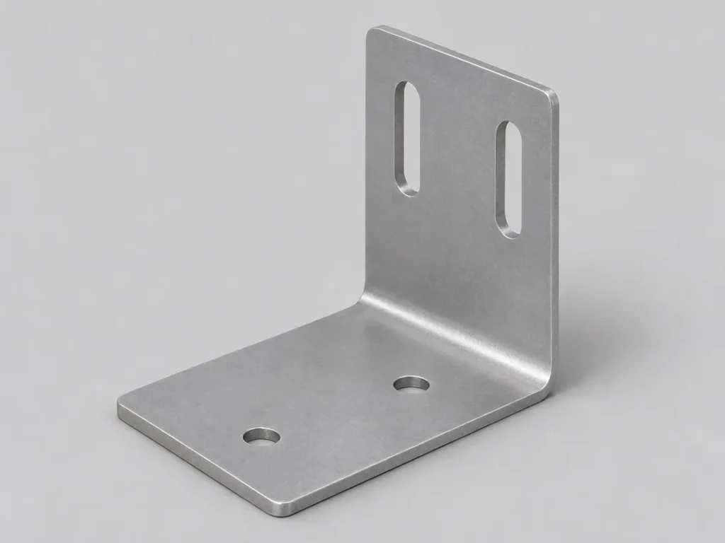
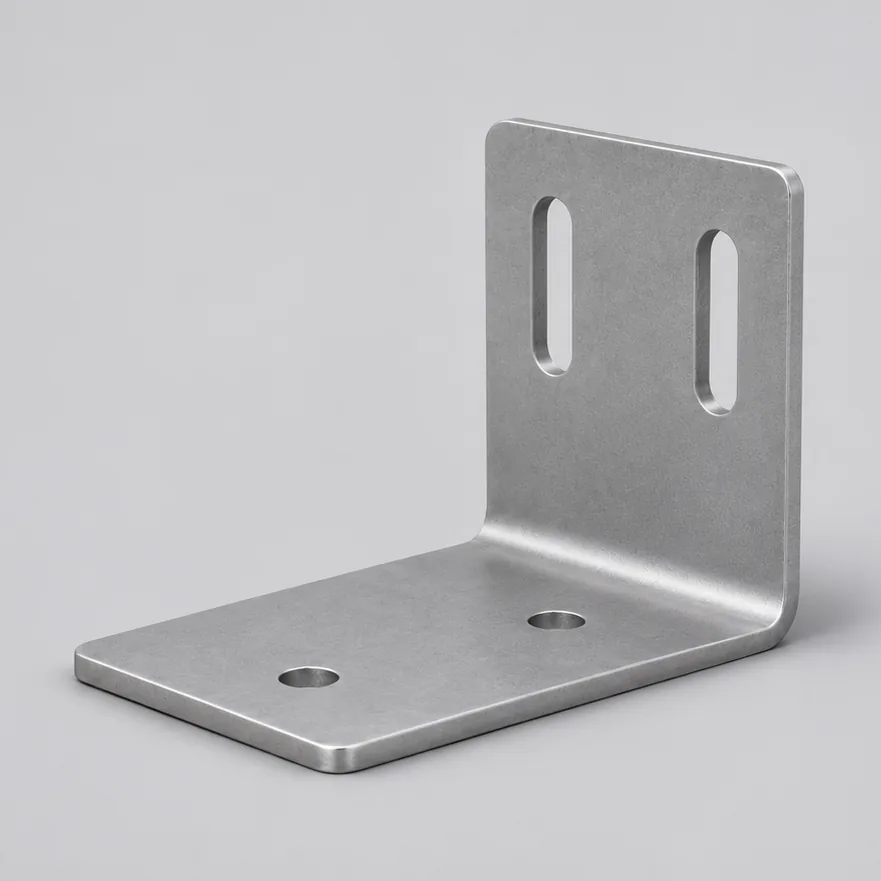
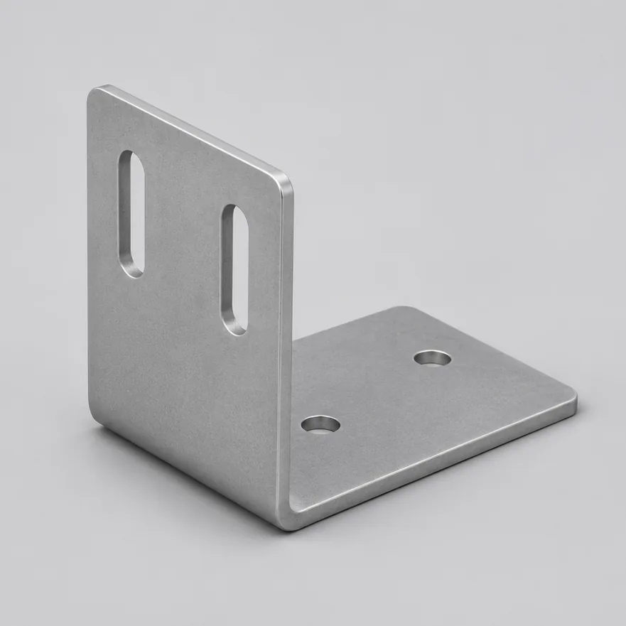
A drawing-based L bracket with bent legs and a mounting-hole or slot pattern for positioning equipment, panels and subassemblies.
| Sheet stock | Specify material grade and thickness |
|---|---|
| Formed geometry | Define leg lengths, bend angle and inside radius |
| Mounting pattern | Supply hole and slot sizes, orientation and locations |
| Finish | Identify coating, masked surfaces and cosmetic faces |
Send a formed drawing and a 3D file if available. Mark the datum for hole positions, finished leg lengths and any slot that controls assembly adjustment.
Highlight holes close to bends, tight inside clearances and surfaces that cannot accept tooling marks. Specify whether dimensions apply before or after coating, and check assembly fit on the first sample.
Product image is a concept illustration. Confirm the final specification and availability in your quotation.
| Sheet stock | Specify material grade and thickness |
|---|---|
| Formed geometry | Define leg lengths, bend angle and inside radius |
| Mounting pattern | Supply hole and slot sizes, orientation and locations |
| Finish | Identify coating, masked surfaces and cosmetic faces |
| Inspection | Specify assembled dimensions and relevant tolerances |
Give the dimensions that control fit on the formed part. If you supply a flat pattern too, state which document controls if a dimension conflicts.
Feasibility depends on sheet thickness, inside radius and tooling. Show the exact location and flag any slot edge that must remain straight after forming.
Specify finish and appearance, then mark threads, grounding surfaces or mating areas that need masking. State whether hole and slot sizes are checked after coating.
A cut-and-bent bracket can suit changing designs or smaller batches. For repeat volumes, compare geometry, tooling, unit cost and inspection requirements before choosing a process.
An enclosure project example for discussing panels, openings and assembly.
Explore detailsA formed bracket concept with fastening holes and bent interfaces.
Explore detailsA drawing-defined mounting concept with pockets, bores and fastening features.
Explore details