Custom Aluminum Mounting Bracket
A drawing-defined mounting concept with pockets, bores and fastening features.
- Material family
- Aluminum
- Process
- CNC milling

COMPONENT DIRECTORY
5 results
A drawing-defined mounting concept with pockets, bores and fastening features.
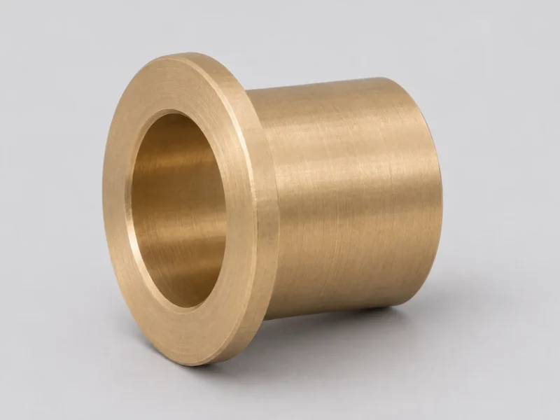
A drawing-defined turned sleeve with an integral flange, for shaft support, axial positioning or a replaceable wear interface.
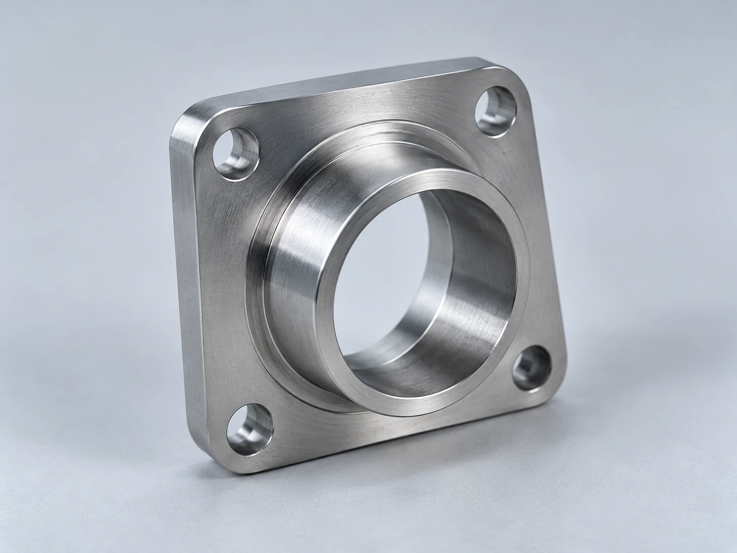
A flange concept with a central bore and a bolted mounting interface.
A turned spacer concept for locating and separating assembly components.
A housing concept with an internal cavity and mounting features.
KEEP EXPLORING
Discuss milled and turned features, material choices and inspection requirements for your custom components.
Explore detailsTechnical Blog · Nov 2026
The information that makes a manufacturing enquiry clearer, more complete and easier to compare.
Read articleDrawing-defined brackets, flanges, spacers and housings. The examples in this directory describe potential project requirements; final feasibility is reviewed against your drawings.
Identify the part’s functional surfaces before selecting a machining route. Prismatic features, pockets and mounting faces often suggest milling; rotational features may suit turning. The complete geometry and workholding determine the final approach.
Material selection affects forming or machining decisions, surface treatment and the way the component behaves in its assembly. Identify an exact grade when it is mandatory. If substitutions are possible, explain the performance requirement instead of leaving the decision implicit.
Mark functional dimensions and reference datums. Separate general drawing requirements from special checks, cosmetic surfaces and reporting requirements. State whether inspection records, material documentation or sample approval are required.
Use one drawing revision for all quotations. Include the required quantity, forecast repeat demand, packaging constraints and delivery destination. Record any permitted alternatives before comparing offers.
Send the current drawing or model, material and finish, required quantity, critical dimensions and your target delivery date. If a detail is still open, identify it so it can be discussed.
Describe the purpose of the prototype and the expected production quantity. Sample scope, tooling, inspection and any later production route should be agreed before an order.
Provide both when available. The model communicates geometry, while the drawing identifies tolerances, threads, material, finish and inspection requirements. Keep matching revision identifiers on both files and identify which document governs conflicts.
Focus on features that control fit, alignment, sealing or function. Mark those dimensions explicitly and use an appropriate general tolerance for other features. Unnecessarily tight requirements can complicate production without improving the assembly.